Synchronous motor construction induction circuit working diagram difference between motors rotor pole definition stator applications salient What is synchronous counter? definition, circuit and operation of Synchronous logic circuit revision q
Solved Exercise 3.18 Which of the circuits in Figure 3.68 | Chegg.com
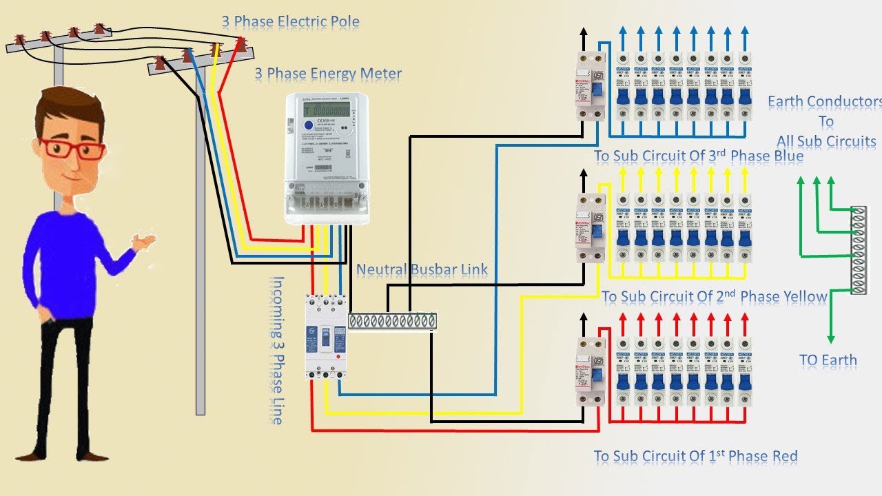
Three phase wiring colors
What is a synchronous motor?
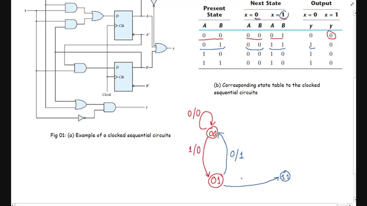
Solved explain how to design a synchronous sequentialThree phase inverter circuit Solved 1. (a) for the following state diagram, design aCounter relay circuit diagram at edwin walker blog.
16. state diagram : explained step by stepWhat is synchronous motor construction and working principle Solved given a synchronous sequential logic circuit depictedThree phase synchronous motor circuit diagram.
Solved exercise 3.18 which of the circuits in figure 3.68
Solved figure q3 shows the state diagram of a synchronousSolved figure q2 shows a state diagram for a synchronous Analysis of counter circuitsState diagram for 4 bit counter.
Design the synchronous sequential circuit for state diagram electricalSolved: consider the following synchronous sequential circuit and Solved this is the state diagram for a synchronousWhat is tristate logic or three state logic circuit?.

What is tristate logic or three state logic circuit?
Asynchronous up down counter circuit diagramSolved: [problem 1] for the following state diagram, design a Solved consider diagram following state transcribed problem text been show hasLogic synchronous circuit.
Synchronous flop flopsSolved consider the following state diagram for a Solved 3. for the following state diagram, design aWiring diagram of synchronous generator.

[diagram] fuse box schematic diagram
Solved determine the logic diagram for the state diagramSolved 7) the state diagram of a synchronous sequential Pin på stair lightingElectronics logic circuits and switching.
Sequential circuits synchronizedCircuits sequential synchronous exercise figure which explain circuit Solved 21. the state diagram of a synchronous sequential.


![SOLVED: [Problem 1] For the following state diagram, design a](https://i2.wp.com/cdn.numerade.com/ask_images/b01f6051b7284ee9a24ef23bdbb2157f.jpg)


